|
|
|
Categories
|
|
Information
|
|
Featured Product
|
|
|
 |
|
|
There are currently no product reviews.
 ;
This Manual (as downloaded) is both informative and comprehensive and has proved to be extremely useful. thoroughly recommended.
;
everything is ok, thank you very much! Product is good, no problems with download!
;
Great site, I always find all the manuals I need and i can't find anywhere else. PDF for the Sony PCM 3348 is complete and scan is good quality. Thank you!
;
It was a complete manual as stated. Very good source for older product manuals. Thanks
;
Scan quality is very good. Price is very reasonable. If you're looking to purchase a copy of this manual, this is the one to get.
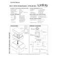
WIRING THE SYSTEM
TURN OFF ALL POWER...
After placing the speakers, you are ready to connect your system. First turn off all audio system power. Use high-quality speaker wire to make your connections. For speaker connections, use at least #18 gauge speaker wire (or #16 for runs over 25 feet) with polarity coding. The side of the wire with a ridge or other coding is usually considered positive polarity (i.e., + ). Also, consult the owner�s manuals that were included with your amplifier, receiver, or television to confirm connection procedures. On the back of the US-1, loosen the bracket screw and rotate the bracket to access terminals. Observe polarities when making speaker connections, as shown in Figure 6. Connect each + terminal on the back of the amplifier, receiver, or television to the respective + (red) terminal on each US-1 speaker. Similarly, connect the � (black) terminals in the same way.
IMPORTANT!
Figure 6. Wiring diagram shows polarity connections for one channel of a stereo or home theater system.
Do not reverse polarities (i.e., + to � or � to +) when making connections. Doing so will cause poor imaging and diminished bass response.
US-1
Receiver or Amplifier
(rear view) (rear view)
Output
+
One Channel Shown
�
Bracket Not Shown
�
+
red terminal = + black terminal = �
ROUTING THE WIRES...
After making your connections, route the wires through either hole in the door, as shown in Figure 7. NOTE: You may need to loosen the bracket screw to open the door further. After you finish connecting your system, return the door to the desired angle and tighten the bracket screw.
Figure 7. This illustration shows how to route the wires through either hole in the US-1 bracket and connect them to the terminals.
(rear view)
US-1
blk
red � Loosen Terminal � Insert Bare End; Tighten Terminal
�
+
Route Speaker Wire Through Either Hole
Output From Amplifier or Receiver
US-1 Theater Pac � Owner�s Manual x 7
|
|
|
> |
|